Skip to content
How to make an LED PCB?
Making an LED PCB (Printed Circuit Board) involves several critical steps, from designing the layout to assembling the components onto the board. The process includes both the manufacturing of the PCB and the installation of the LED components on the PCB.
Here’s a detailed guide on how to make an LED PCB:
1. Designing the PCB Layout
The first step is designing the layout for your LED PCB. This involves determining where the LEDs, resistors, power connections, and other components will be placed on the board.
- Select PCB Design Software: Use PCB design software like CAD, Altium Designer to create your schematic. These programs allow you to design the circuit layout, including the pathways that the electrical signals will follow.
- Determine Circuit Configuration: Decide how your LEDs will be connected. Common configurations include series, parallel, or a combination of both. The arrangement will depend on factors like voltage and current requirements.
- Draw the Schematic: Using the design software, create a schematic that represents the electrical connections between components such as LEDs, resistors, and the power source. Ensure the layout follows the required circuit design principles, like current-limiting resistors for LEDs to prevent burning out.
- Design PCB Traces and Pads: After creating the schematic, you’ll switch to the PCB design mode, where you’ll define the physical layout of the PCB, such as the traces (conductive pathways) and pads where components like LEDs and resistors will be soldered.
- Thermal Considerations: For LED PCBs, particularly those handling high power, ensure proper heat dissipation by placing thermal vias (holes that transfer heat from one layer of the board to another) or using thicker copper layers to improve heat management.
- Final Design Check: Double-check the design for potential errors, like overlapping traces, and ensure the layout is optimized for electrical performance and manufacturability.
2. Choosing the PCB Material
The material of your PCB will influence its performance, particularly in terms of heat dissipation, flexibility, and durability. The most common materials used for LED PCBs are:
- FR4 (Fiberglass): This is a widely used material for general-purpose LED PCBs, offering good electrical insulation and structural stability.
- Aluminum (Metal-Core PCBs): Aluminum-backed PCBs are ideal for high-power LED applications because they provide excellent heat dissipation. These are commonly used in LED lighting for automotive, streetlights, and industrial applications.
- Flexible Polyimide (for Flexible PCBs): If your design requires a bendable PCB, such as for LED strips, you might opt for flexible polyimide substrates.
3. Fabricating the PCB
Once your design is complete, the next step is fabricating the physical PCB. This involves converting your digital design into a real circuit board. You can either fabricate the PCB yourself (if you have the required equipment) or outsource the job to a professional PCB manufacturer.
- Generate Gerber Files: After finishing the design in your PCB software, export the layout into Gerber files. These files are the industry standard format for PCB fabrication and include the data for each layer of your PCB (e.g., copper layers, solder mask, and silk screen).
- Select a PCB Manufacturer: If you’re outsourcing, send the Gerber files to a PCB manufacturer like us M2PCB, or local manufacturers who offer custom PCB production.
- Choose Layer Count and Thickness: For an LED PCB, you might opt for either single-layer or multi-layer PCBs depending on the complexity of your design. Choose the copper thickness (commonly 1 oz/ft² to 2 oz/ft²) based on the current handling requirements.
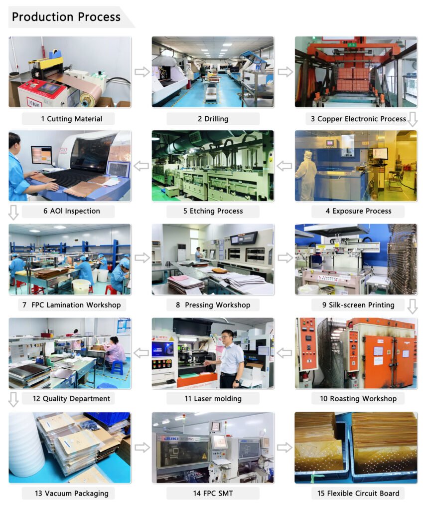
- Manufacturing Process: Below picture is about the process of flexible PCB.
- Quality Inspection: Once the PCB is fabricated, it undergoes a quality check to ensure there are no shorts, open circuits, or other defects.
4. Sourcing Components
Now that the PCB is ready, you need to source the LED components and other necessary parts. These include:
- LEDs: Choose LEDs based on your voltage, brightness, and color requirements. Common LED types include SMD (Surface Mount Device) LEDs or through-hole LEDs.
- Resistors: Choose resistors to limit current through the LEDs and protect them from excessive power.
- Connectors and Power Supply: If needed, include connectors for power input or additional circuitry, as well as a compatible power supply.
5. Assembling the PCB
The next step is to assemble the components onto the PCB by soldering. You can either do this manually or through an automated process if you’re producing the PCB in large quantities.
- Surface Mount or Through-Hole Components: For surface mount LEDs, the components are placed directly onto the PCB pads, while through-hole components require the insertion of leads into drilled holes.
- Soldering the Components: a, Manual Soldering: If you’re working on a small batch or prototype, you can manually solder the LEDs and resistors using a soldering iron. b, Reflow Soldering (for SMD components): In larger production runs, the components are placed onto the PCB using a pick-and-place machine, and then the board is passed through a reflow oven. In the reflow oven, the solder paste melts, creating permanent connections between the components and the PCB. We also support SMT, SMD soldering if you need the service.
- Quality Check: Once the soldering is complete, inspect each connection for cold joints or bridges (where solder connects components unintentionally). A multimeter can be used to check for proper electrical connections.
6. Testing the PCB
After assembly, the PCB should be tested to ensure that everything is functioning as expected. This is a critical step to verify that your LED circuit works without any issues.
- Visual Inspection: Inspect the board for any visible defects, such as bad solder joints or misplaced components.
- Power On the Circuit: Apply power to the PCB and check that the LEDs light up correctly. Ensure there are no shorts or open circuits.
- Check Voltage and Current: Use a multimeter to measure the voltage and current at different points in the circuit to ensure that they match your design specifications.
- Thermal Testing: For high-power LED PCBs, perform a thermal test to check if the PCB properly dissipates heat. Overheating can cause the LEDs to degrade quickly, so this is an important step.
7. Final Assembly and Mounting
Once the PCB passes testing, it’s ready for final installation. This could involve placing the LED PCB into a housing (e.g., in the case of an LED bulb) or attaching it to a heat sink (for high-power applications). LED strips may have an adhesive backing for easy mounting.
Example Applications:
- LED Strips: The PCB might be flexible and designed to be attached to surfaces like walls or ceilings for accent lighting.
- LED Bulbs: The PCB may be placed into a heat-dissipating enclosure for general lighting applications.
- Custom Displays: The LED PCB can be integrated into larger systems, such as digital signage or decorative lighting.
Making an LED PCB involves a series of steps, starting from designing the PCB layout, choosing appropriate materials, and fabricating the board, to sourcing components, assembling, and testing. Whether you’re creating a simple LED strip or a more complex high-power LED board, understanding these steps ensures a functional and efficient LED lighting solution. This process requires careful attention to design, heat management, and component selection to achieve the best results for your LED lighting application. Certainly, you also can ask us to help to design and produce LED PCB, we support one-stop led pcb solution, from design to mass production, just send a message to me.