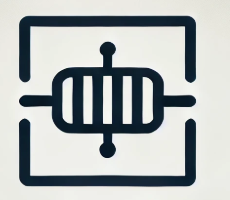
Electric schematic symbols are the building blocks of circuit design, enabling engineers to represent components and their interconnections in a clear and standardized manner. These symbols act as a universal language, bridging the gap between theoretical concepts and practical implementations. In this article, we will explore the role of electric schematic symbols, common examples, their significance in circuit design, and how to interpret them effectively.
What are Electric Schematic Symbols?
Electric schematic symbols are graphical representations of electrical and electronic components used in circuit diagrams. Each symbol corresponds to a specific component, such as a resistor, capacitor, or diode, and provides information about its function and connections within the circuit. These symbols are standardized to ensure consistency and comprehension across different industries and region.
The Common Electric Schematic Symbols
Here are some of the most widely used electric schematic symbols:
1 Resistors: Represent components that limit current flow.
- Symbol: Zigzag line (US standard) or a rectangle (European standard).

2 Capacitors: Depict devices that store electrical energy.
- Symbol: Two parallel lines (polarized capacitors have one curved line).

3 Inductors: Represent coils of wire that store energy in a magnetic field.
- Symbol: Series of loops or a rectangle with lines extending outward.

4 Diodes: Indicate components that allow current to flow in one direction.
- Symbol: A triangle pointing to a line.
5 Transistors: Represent switching or amplifying devices.
- Symbol: Arrows and lines indicating base, collector, and emitter connections.

6 Integrated Circuits (ICs): Represent complex circuits within a single package.
- Symbol: A rectangle with labeled pins.
7 Power and Ground Symbols: Indicate voltage sources and return paths.
- Symbol: Vertical line(s) for power, a triangle or horizontal line for ground.

Why Electric Schematic Symbols are Important in Circuit Design?
Schematic symbols are vital for several reasons:
1 Clarity: They provide a clear and concise way to represent complex circuits.
2 Communication: Serve as a universal language, allowing engineers from different backgrounds to collaborate effectively.
3 Documentation: Create a permanent record of the circuit for future reference, debugging, or replication.
4 Error Reduction: Simplify circuit analysis, helping to identify potential design flaws early.
What Types of Electric Schematic Symbols?
Electric schematic symbols can be categorized based on their function:
1 Passive Components: Resistors, capacitors, and inductors.
2 Active Components: Transistors, diodes, and integrated circuits.
3 Power and Ground: Symbols representing voltage sources, batteries, and ground connections.
4 Input/Output Devices: Switches, relays, LEDs, and sensors.
5 Connectors and Interconnections: Terminals, bus lines, and jumper wires.
These categories make it easier to understand a circuit’s purpose and functionality.
Reading Electric Schematics
Reading and interpreting electric schematics is the best way to understand how schematic symbols relate to real components. Here’s how to approach it:
1 Start with the Power Supply: Locate the voltage sources and ground to identify the circuit’s reference points.
2 Follow the Flow: Trace the connections from the power source to the load, observing how components interact.
3 Identify Groups: Look for functional blocks (e.g., amplifiers, filters) to simplify analysis.
4 Cross-Reference with Parts: Compare symbols with actual components on the PCB or breadboard for practical understanding.
Electric schematic symbols are the foundation of circuit design, offering a standardized way to represent components and connections. By understanding these symbols, engineers can effectively create, analyze, and communicate electronic designs. Learning to read and interpret schematics not only bridges the gap between theory and practice but also ensures that designs are efficient, reliable, and easy to replicate. Mastering schematic symbols is a crucial step for anyone venturing into the world of electronics.

